| |
160m to 6m High perfomance Front End subsystem |
|
| |
|
|
|
|
| |
Martein Bakker, PA3AKE has designed a HF Front End down converter based in part on the H-Mode Mixer or switched mixer developed by Colin Horrabin, G3SBI, that offers extremely third-order intermodulation intercept figures and high dynamic range.
Features are an MDS of -133dBm, SSB bandwidth, IIP3 of +51,2dBm with an IMD3DR (Third order intermodulation dynamic range) of 122.8dB on 40M!
All this is achieved with no special/expensive components.
Certainly, Martein’s design has broken the magic 120dB IMD3DR boundary on real life not on simulation software.
Due its notable features I couldn't resist to build a replica.
Martein has published a comprehensive documentation at his web site:
http://www.xs4all.nl/~martein/pa3ake/hmode/ |
|
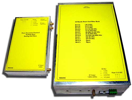
Front End subsystem
|
|
| |
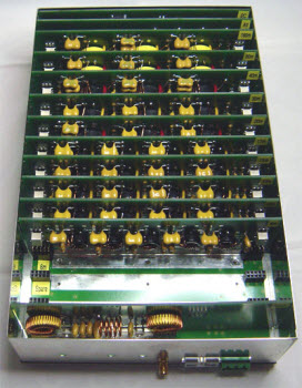
BPF bank with removed cover
|
|
The Front End subsystem comprises two main units:
Band Pass Filters box unit
Attenuator board
12 band pass filter boards
IF notch board
BPF I2C controller board
Front End box unit
H - Mode Mixer
9MHz Diplexer
SSB/CW Roofing Crystal Filters
Mixer I2C control
Local Oscillator
DDS technology based
The Band Pass Filter bank assembly includes filter boards for:
160m-80m-40m-30m-20m-17m-15m-12m-10m and 6m
Two extra slots for spare bands
I2C Bus control board
Step attenuator board
9MHz IF Notch board.
Enclosure size is 25cm x 16cm x 6cm (9.84x6.29x2.36inch).
Total weight with boards is 1.6 Kg.
|
|
| |
|
|
|
|
| |
|
|
|
|
| |
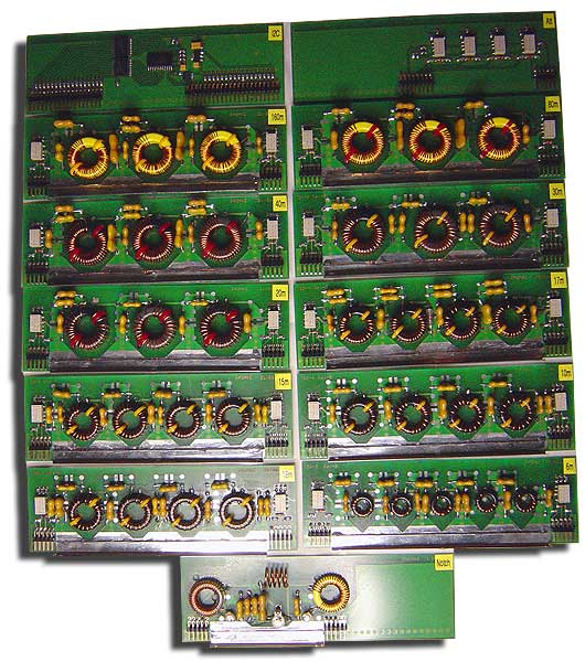
BPF bank set of PCBs |
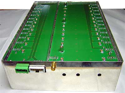
Boxed BPF Motherboard bottom view
| |
To achieve good stop band performance the bottom compartment has been divided in two sections.
That also improves stop band in the VHF region.
M2 brass nuts to fix the boards are soldered on the ground plane in order to improve ground connection.
The motherboard ground plane is soldered to the enclosure walls resulting a robust assembly.
|
|
|

Boxed BPF Motherboard top view.
Filter boards removed. |
|
| |
|
|
|
|
| |
 |
|
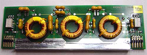
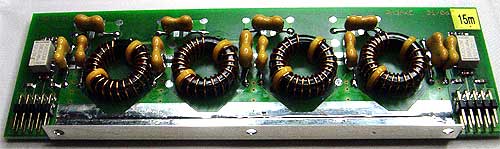
Filter boards
They are three kinds of filter boards according with the toroid core size used:
- T94 core for 160m, 80m,40m,30m and 20m filter boards.
- T80 core for 17m,15m,12m and 10m filter boards.
- T50 core for 6m filter board. |
|
| |
T94 core board type for 160m band. Three sections BPF configuration. |
|
|
|
| |
 |
|
 |
|
| |
T80 core board type for 15m band. Four sections BPF configuration. |
|
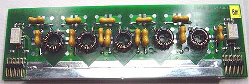
T50 core board type for 6m band. Five sections BPF configuration. |
|
| |
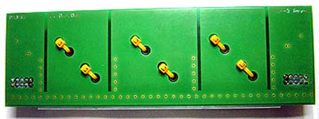
Filter board rear view detail.
Coils are secured in place using cable ties. |
|
Relays on filter boards are small SMD telecom grade with DC "soak" contacts.
Martein recommends using Suflex 2.5% Polystyrene capacitors on all filters but due availability issues I used instead 1%/500V mica capacitors.
To reduce IMD, the flux inside the cores has to be keep as low as possible, for so the filters has been designed with inductance values as high as practical.
For the same reason toroidal cores grade were selected taken in account its μ value.
There are no variable capacitors. Fine tuning is performed moving the distribution of turns around the toroid.
A carefully PCB design improves the filter response. The backside of the PCB has vertical cuts on ground plane to prevent ground currents flowing from underneath one toroid to the next. With this cuts -100dB stop band is reached. |
|
| |
|
|
|
|
| |
|
|
| |
Alignment of filters
This is the tough part of the project.
Alike others filters with the same topology, toroid cores and fix capacitors values, the precise alignment of the BPF's to get minimal insertion loss and ripple in the pass band is performed moving the distribution of turns around the toroid, this ask for patient and time. |
|
| |
|
|
| |
|
|
|
|
| |
|
|
| |
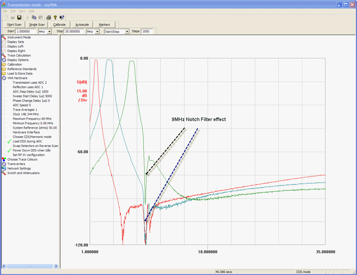
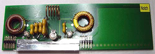
Notch filter board
IF 9MHz attenuation: > 90 dB
The 9MHz IF frequency is blocked as much as possible before reaches the mixer.
In order to minimize the spectrum exposed to the notch filter it is placed in the signal chain after the BPF bank. | |
|
|
| |
|
|
|
|
| |
 |
|
| |
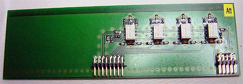
0 to 30 dB Step Attenuator board
SMD telecom grade relays with DC "soak" contacts switching respectively 2dB, 4dB, 8dB and 16dB attenuation.
The IIP3 of the front end will be around +80dBm when the attenuator is set at 30dB! |
|
|
|
| |
 |
|
| |
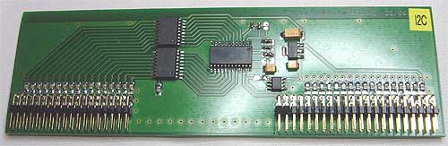
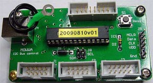
I2C control board
The twelve BPF filters and the Step Attenuator are relay-switched; the control is handled through I2C Bus protocol.
The board has a PCF8575 16 bit I2C Bus I/O-extender, two ULN2803A 8-bit relay drivers and 12V and 5V LDO regulators. |
|
|
|
| |
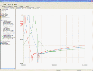
(Click on picture to enlarge) |
|
| |
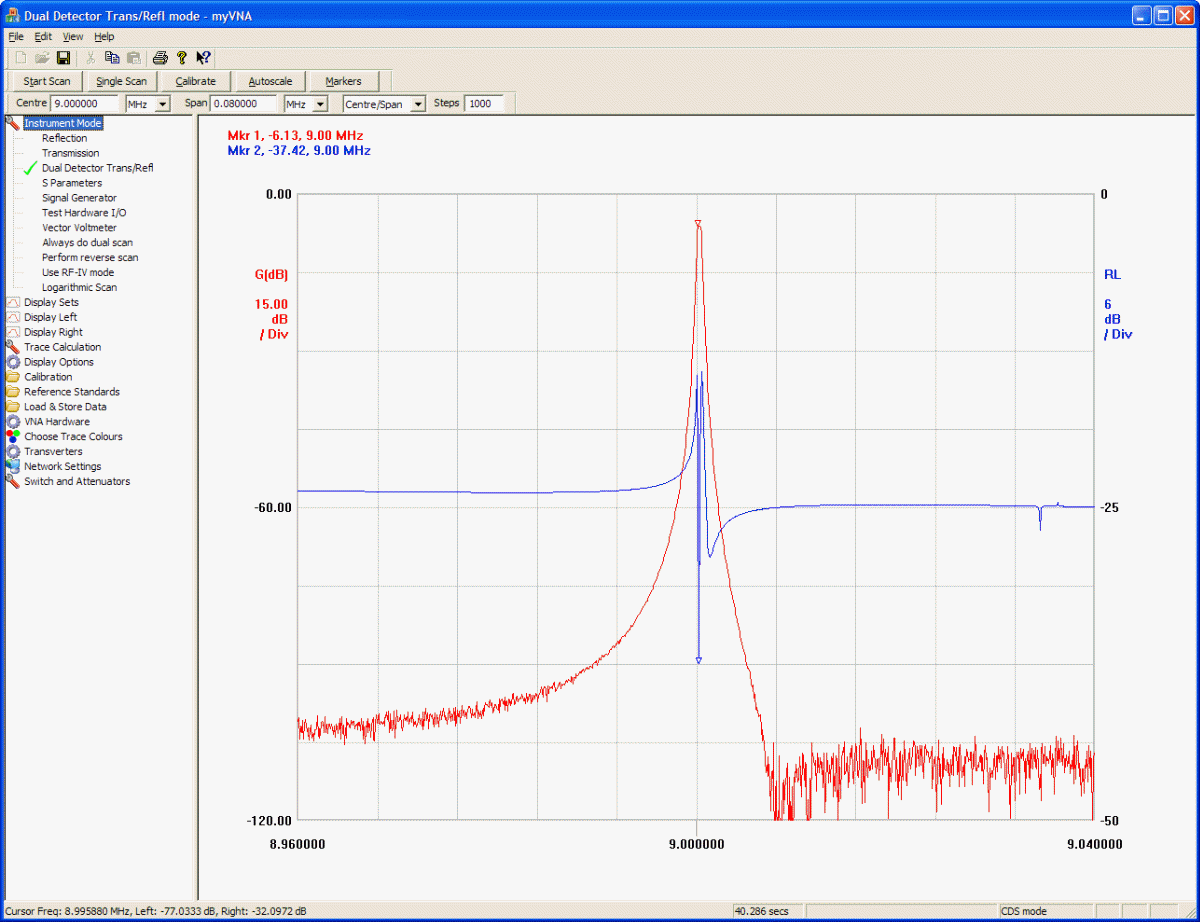
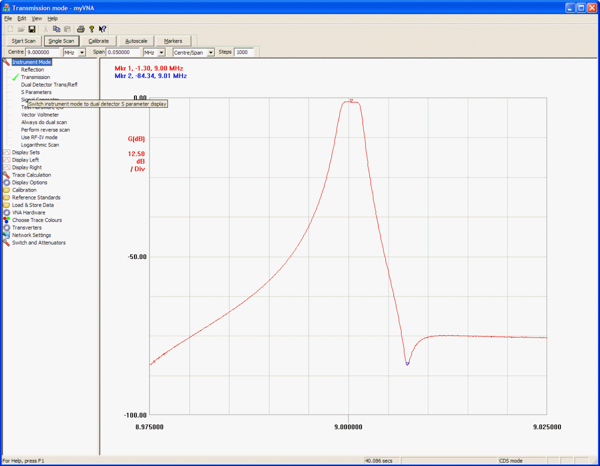
160m-80m-40m bands filters plot |
|
|
|
|
|
|
|
|
| |
USB-I2C Bus control Module for Front End project
(USB powered)
Martein’s Front End project does not gives software support to control the I2C Bus.
To solve this I designed a solution based on a PIC microcontroller 18F2455. It includes I2C Bus and USB peripherals that let's handle the Front End.
The software running on the PC takes control of all functions of the front end. In addition, it includes capability to change manually data and addresses on the I2C bus for experimentation purposes.
The Status bar indicates if the PIC module is connected to the USB port. It runs under Windows 2000, XP, Vista and Windows 7 32/64 bits Operating Systems.
(Windows 2K users need to update Framework from Windows Update site)
The PIC I2C control module receives power from the USB port.
It provides Reset push-button, three IDC 10 pins connectors for I2C lines matching with the standard pin out of the project; auxiliary connector for program the PIC on circuit (ICSP capability) and Expansion Bus, IDC 16 pins connector, for upcoming updates of the project. |
|
Assembled USB-I2C Bus control Module |
|
| |
|
|
|
|
| |
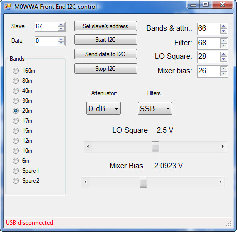
Graphic User Interface on PC (download) |
|
USB-I2C Bus Control Module program software for Front End project
Controls
| BPF bank:
- Bands
- Attenuator
- Manual control
- I2C addresses
- Status bar |
H-Mixer:
- Filters
- Squarer DAC
- Bias-point DAC
|

USB-I2C bus control module manual |
|
|